Disassembling a LeCroy 9400
(125MHz Digital Storage Oscilloscope)
The LeCroy 9400 Oscilloscope is now very much a discontinue product but for hobbyists its still a very useful tool. Originally the scope cost several 1000s of USD, but can be bought for around 200 - 300 USD depending on options. Modern LeCroy scopes are still available and the cheapest for about 800USD and gets around 500MHz/2Gs and go all the way up to multi-100,000 USD devices and you can find them at their
web site. You can still check out the original brochure for the 9400A (175MHz version of the scope) at this
web site.
The LeCroy 9400/9400A can also connect to a GPIB connection for both data acquisition, triggering and general control. There are many commercial tools and a few free ones such as
FCS2 that allows control and capture from Linux.
 |
| GPIB cable connected and device ID set to 04 courtesy of Kennel System Blog |
Both Kurt and Ko4bb have the manuals and service manuals scanned and online. Below are the ones related to the 9400;
The general operations manual is useful as you might imagine for working out how to do sequential storage, but the service manual is invaluable in showing how to enter the 'hidden' test menu and run various tests to check the failure point in the scope. It also has schematics so you could feasibly replace most of the scope although I found most common failures were in the two or three custom chips on this scope (HADACC and the HVV200).
Its also a great idea to join the
LeCroy mailing list as there are many LeCroy enthusiasts out there that can assist or share stories - its a great little group.
Common Failures
My scope CH2 has failed with a constant 500KHz sine wave and I will discuss swapping the pre-amp boards to fix it below. It would show a 500KHz sine wave which was always scaled to the
voltage level selected. This hinted that it wasn't the input stage, and
more likely the pre-amp board.
First lets look at common failures that others have had with their scopes. Another Japanese LeCroy enthusiast had similar problems to the one my scope had, in his case
CH1 had a sine wave wobble.
 |
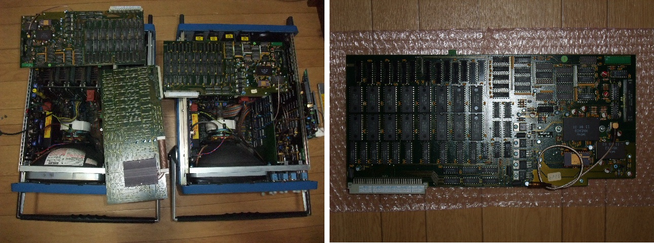
| Left; Swapping parts to repair pre-amp issues. Right; Pre-Amp board courtesy of Kennel System Blog |
Another issue that appears to be possible with the scope is that the pre-amp boards can over-heat if the heat sink isnt attached properly then it can crack and start smoking like this guy shows.
Another source of issues is the input stage near the BNC which means completely disassembling the scope which can be a real pain. This could be due to relay failure, or the gain amplifiers on the main board like shown below.
Disassembling the LeCroy 9400
[ WARNING: Very high voltages 110 - 240V from the socket, and 40Kv from the CRT ]
As above my scope's CH2 has failed with a constant 500KHz sine wave which was always scaled to the
voltage level selected. So, given the common failures I saw with other scopes then this hinted that it was not the input stage and
was more likely the pre-amp board.
 |
| Remove the upper casing screws |
 |
| Remove upper case from middle on both side evenly |
 |
| Remove screws from cross-board connector |
 |
| Remove screws from Securing Bar |
 |
| Boards being secured by Securing Bar |
 |
| Remove screws from PSU back plane and Securing Bar |
 |
| Remove Securing Bar |
At this point it should be possible to swap the CRT board, tune the focus and intensity of the CRT, swap the GPIB board, pre-amp/capture boards, and trigger boards, as well as change fuses and other settings.
Main Board, CRT or PSU access
Disassembly from here on gets much more challenging, and you might seriously damage your scope and you run the risk of getting a nasty shock if you arent careful.
 |
| In order to remove the PSU / Back panel you need to pull out ...the GPIB cables from the GPIB board, RS232 cable from just below the CRT (right) and the Power Connectors as shown. |
 |
| Remove Feet, this will release the back plate |
 |
| Not necessary but these screws release the PSU bricks from the back plate (Top and Bottom of grill) |
 |
| Back Plate, PSU Bricks and PSU Back-Plane shown completely disassembled |
 |
| A view from back of scope after Back Plate was removed |
 |
| Another view from back of scope after Back Plate was removed |
 |
| View from Top |
 |
| Remove CRT gun controller board |
 |
| Gun Controller Board Close Up |
 |
| Remove Cross Card connector |
 |
| Cross Card Close Up |
 |
| Remove First board, Starting from Right (GPIB Board) |
 |
| GPIB Board Close Up |
Notice this board has a connector on the top, this actually allowed for the TV trigger option and other options to be fitted to the top of the scope.
 |
| Next pop CH1's connector to the main-board (foreground you can see the ribbon cable for the front display) |
 |
| Close Up of Pre-Amp capture board (Front) |
 |
| Close Up of Pre-Amp capture board (Back) |
 |
| Removing CH2, exactly same as CH1 |
 |
| Removing the Trigger Board (Cables are for NEG/POS edge) |
 |
| View from back once all cards are removed, including CRT control card on right |
 |
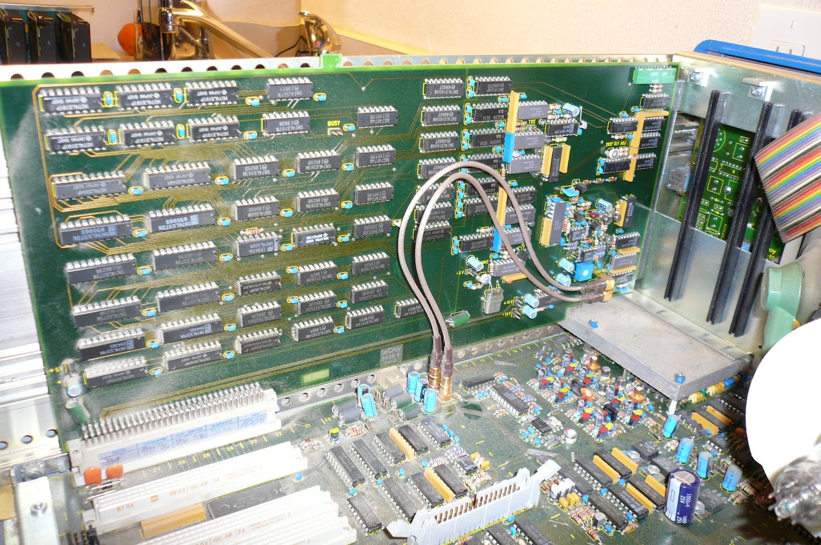
| Main Board view from above |
 |
| Main Board view of BNC input on left side |
 |
| Main Board view from below, BNC input on bottom right |
 |
| View of BNC adjustment screws |
 |
| View of BNC adjustment screws |
 |
| View of BNC adjustment screws |
 |
| Main Board View Bottom from Back of Scope |
In order to fully remove the main board you have to remove the metal blocks and carefully lift he main board. The reason for this is the riser card near the BNC CH1/CH2 inputs (as seen below on top right of board just above the BNC) and the IC mounted just behind the reference signal connectors. (as seen below just to the right of the CH1/CH2 connectors).
 |
| Main Board fully removed from top |
 |
| BNC close up from top |
As you can see the riser card at the top of this photo (slightly blue, sticking up from behind BNC CH1/2 housing), and the IC just behind the two reference-signal connectors both block easy removal of the main board.
Finally all back together and working
Putting it all back together was a little nerve racking, esp. as I had no ESD strap to ground myself. Questions were buzzing around my head; would it work, had I broken something, is it so old it just died naturally on the OR table whilst I was working on it???
It powered up and both CH1 and CH2 are now good to go. You might notice some roll off/on of the reference signal and this is to do with the probe not being correctly matched but its enough for testing.


